2026-10-01 · 7 min · By Alcott Dube
How to build a parametric model that survives design changes
I build change-tolerant parametric models by constraining sketches deliberately, choosing stable references, and naming the dimensions that carry design intent before adding detail.

To build a parametric model that survives change, fully constrain its sketches around deliberate datums, reference stable geometry, and give controlling parameters meaningful names. I separate structural features from finishing details, then test realistic dimension changes to check both regeneration and design intent.
Define design intent before creating features
I start by writing down what should change and what must remain true. For a mounting plate, width might vary while the mounting holes stay 12 mm from adjacent edges. Another plate might need a fixed hole pitch to match an existing bracket. Those requirements can produce identical geometry initially, but they need different dependencies.
SolidWorks describes design intent as the behaviour built into a model through dimensions, relations and feature choices. I translate that into a short specification: variable dimensions, fixed interfaces, symmetry requirements and expected size limits. A note saying 'keep centred' is useful only when a relation or feature actually enforces it.
For a worked example, I’ll use a plate measuring 120 mm long, 80 mm wide and 4 mm thick, with four 6 mm holes. I’d identify length, width, thickness, hole diameter and hole centre distance from the edges as inputs. I wouldn’t parameterise every radius before knowing whether anyone needs to change it.
Fully constrain sketches without fixing everything
I position the first sketch against the origin rather than drawing nearby and fixing it in place. For a symmetric plate, I centre a rectangle on the origin and dimension its length and width. That gives later features a useful centre reference and makes the intended movement predictable when either dimension changes.
Autodesk’s Fusion documentation distinguishes geometric constraints, which control relationships, from dimensions, which control size and position. I use both. Parallel lines should have a parallel relationship; equal circles should share an equality constraint where that equality is intentional. Matching two typed values is not the same as connecting them.
Before leaving a sketch, I check its constraint status and investigate any remaining movement. Dragging geometry helps reveal missing relationships, but it isn’t proof of completeness. I also avoid fixing whole sketches merely to remove free movement. A fully constrained sketch can still encode the wrong behaviour, so I change one dimension and watch which geometry moves.
Choose stable references for sketches and features
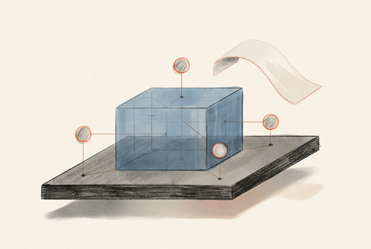
I prefer origin planes, axes and deliberately constructed datum geometry when those references describe the requirement. A sketch on a filleted face inherits a dependency on that fillet. If the rounding changes or disappears, the sketch may lose its support. A suitable datum plane avoids that particular dependency, although its own parents still matter.
For the plate, I’d consider a symmetric extrusion about the main sketch plane. That keeps the centre plane stationary as thickness changes. If the bottom face is the mounting interface instead, a one-sided extrusion from that interface is more honest. Symmetry is not automatically better; the assembly requirement decides which surface should stay put.
I treat projected edges as borrowed geometry. Each projection needs a reason because it can introduce another dependency to inspect after an upstream edit. Referencing a genuine mating interface is sensible. Projecting a convenient silhouette from a finishing feature usually isn’t. I keep required projections, but avoid filling a sketch with geometry it doesn’t use.
Keep sketches small and feature order deliberate
I avoid putting the outline, mounting holes, recesses and decorative cut-outs into one sketch. A large sketch concentrates relationships and makes failures harder to isolate. For this plate, I’d separate the base profile from the mounting-hole layout, then add pockets or other functional cuts as their own features. That separation follows likely edits, not an arbitrary entity limit.
I normally establish the main volume and functional interfaces before adding edge treatments. Fillets and chamfers often depend on edges that earlier operations can split, merge or remove. Keeping non-functional finishing features late reduces the number of downstream features exposed to those changes. It doesn’t make edge references immune to failure.
There are exceptions. A radius required for a manufacturing operation or a mating condition may belong earlier. I place it where its dependencies make sense, rather than following a blanket rule. I also use patterns when repetition is part of the requirement, checking the direction and instance count instead of assuming repeated geometry expresses the right relationship.
Name parameters and features by what they control
I name the dimensions someone is likely to edit: plate_length, plate_width, plate_thickness, hole_diameter and hole_edge_offset. The last name needs a definition: distance from the hole centre to the adjacent straight plate edge. Calling it edge_clearance would be misleading if someone interpreted that as the material between the hole boundary and the edge.
Fusion supports named user parameters and expressions; SolidWorks provides global variables and equations for related control. I use a single governing value where dimensions genuinely share a requirement. With a symmetric four-hole arrangement, the spacing across the width can be derived from plate_width minus twice hole_edge_offset. I don’t maintain that spacing as another independent input.
Feature names should explain purpose rather than repeat the software’s default label. I’d use mounting_plate, mounting_holes and outer_edge_round. I rename the important sketches too. I skip elaborate naming codes unless a team already depends on them. The useful test is whether another designer can identify the correct edit without opening six unrelated features.
Control external references between parts
A model can have tidy sketches and still depend on an assembly state that nobody remembers. SolidWorks documents external references as relationships to geometry outside the current part. I use them when a component must follow a real interface, but I want the source and purpose to be obvious before the model leaves my hands.
If the plate’s holes must match a bracket, I choose which component owns the mounting pattern. I don’t let both parts drive each other. For several related components, a shared layout or master reference can make ownership clearer. That adds something to maintain, so I wouldn’t introduce it for an isolated plate without a practical reason.
Before handover, I inspect external dependencies and record which files or components are required. I don’t break links merely to make the dependency list look clean. Removing a relationship changes future behaviour. If a design needs to become independent, I make that a deliberate revision and test it without its former source available.
Test parameter changes before handing over the model
I test changes while the feature history is still short. For the example plate, I’d try widths of 60, 80 and 110 mm, lengths of 90, 120 and 160 mm, and thicknesses of 3, 4 and 6 mm. I vary one input at a time first, then test a few combinations, including the smallest footprint with the greatest thickness.
A successful regeneration is only the first check. I measure hole centre offsets, verify symmetry, inspect minimum material around holes and confirm that cuts still pass through where required. A cut that must always penetrate the plate should use an appropriate through extent, not a fixed depth that happens to exceed today’s thickness.
I also try an invalid input. At 24 mm width with two opposing 12 mm centre offsets, hole positions coincide. I want that limit documented, or checked through suitable automation, rather than silently accepted. For handover, I record the tested range, intended edit points and known limits. I keep that record beside the model, where the next edit starts.
Questions people ask
Should every sketch be fully constrained?
I fully constrain sketches that control production geometry. During exploration, I may leave movement available deliberately, but I resolve it before handover. Full constraint removes unintended freedom; it doesn't prove the design intent is correct.
Why does my parametric model break when I change a dimension?
I first check for a lost reference, conflicting sketch relationships or geometry that becomes impossible at the new size. A disappearing edge can break several dependent features. I investigate the earliest failing feature before repairing anything downstream.
Is it better to sketch on a face or a reference plane?
I choose the reference that represents the requirement and has suitable dependencies. A reference plane is useful when a sketch must remain independent of changing faces. A face reference is appropriate when following that face is intentional.
Which dimensions should I turn into named parameters?
I name dimensions that control expected variations, repeated requirements or fixed interfaces. I derive dependent dimensions from those inputs rather than creating competing controls. Naming every dimension usually adds more maintenance than clarity.