2026-09-30 · 7 min · By Alcott Dube
How to model cad parts for manufacturing, not renders
I model around the manufacturing process, then specify tolerances, draft and access so the finished part works without paying for precision it doesn't need.
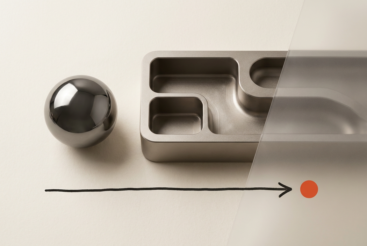
I model parts for manufacturing by choosing the production process first, then building in tool access, suitable wall thickness and the geometry that process needs. I specify tight tolerances only where function requires them, and check the model and drawing with the supplier before release.
Choose the manufacturing process before detailed modelling
A render doesn't care how a cutter reaches a pocket. A mould does care how the part leaves the tool. Before detailed modelling, I write down the material, expected quantity, mating components, loads and surfaces people will see or touch. These decisions narrow the process options. An aluminium bracket needed in quantities of ten deserves a different starting point from a plastic enclosure needed in quantities of ten thousand.
I then identify the likely manufacturing direction: cutter access for machining, mould opening direction for injection moulding, or bend sequence for sheet metal. This isn't a commitment to a particular supplier. It's a way to avoid building the whole design around geometry that later needs an extra setup, a moving mould component or an inaccessible bend.
I keep the first model plain. Mounting faces, interfaces and the outer envelope come before cosmetic grooves and edge treatments. If the process is undecided, I compare two simple versions rather than polishing one. I also ask for an early feasibility review while changing the architecture is still cheap. A supplier can challenge my assumptions before those assumptions become dependencies across an assembly.
Set tolerances from fit and function, not decimal places
I start tolerancing with the interfaces that can make the assembly fail. A locating pin, bearing seat or sealing face needs a defined relationship to its mating part. An external face with generous clearance usually doesn't. Adding decimal places to a model dimension is not a substitute for deciding how much variation the assembly can accept.
For a simple clearance example, suppose a shaft is 10.00 mm with a tolerance of plus or minus 0.02 mm. A hole of 10.10 mm with the same tolerance gives a diametral clearance between 0.06 mm and 0.14 mm. Those numbers are illustrative, not a recommended fit. I would check whether that range suits the load, movement, temperature and assembly method before specifying it.
Asme's Y14.5 standard provides the framework for communicating dimensional and geometric requirements. I use datum references to make the intended relationships explicit, rather than scattering tight size tolerances across unrelated features. Hole position and face orientation can matter even when individual sizes pass inspection. I also check tolerance accumulation across the assembly: several acceptable parts can still produce an unacceptable gap when their variations combine in the wrong direction.
Design machined pockets for cutter access
For a machined part, I inspect every pocket from the cutter's point of view. A rotating end mill leaves a radius in an internal corner. If I draw a sharp internal corner, I'm either asking for a different operation or leaving the supplier to query the model. Neither is a sensible default for a corner that has no functional purpose.
I prefer generous internal radii and pockets that don't force a small cutter to reach a long way. Protolabs' milling guidance treats feature dimensions and tool access as manufacturing constraints, not cosmetic preferences. I don't turn a single depth-to-width ratio into a universal rule: material, cutter diameter, tool reach and the required finish all affect what's practical.
Where a square mating component must sit inside a pocket, I consider corner relief instead of demanding square machined corners. I also review which faces need machining and how the stock will be held. A hole on another face may mean another setup. Before retaining it, I ask whether moving it, making it accessible from an existing direction or changing the assembly method preserves function with less work.
Add moulding draft and control wall thickness
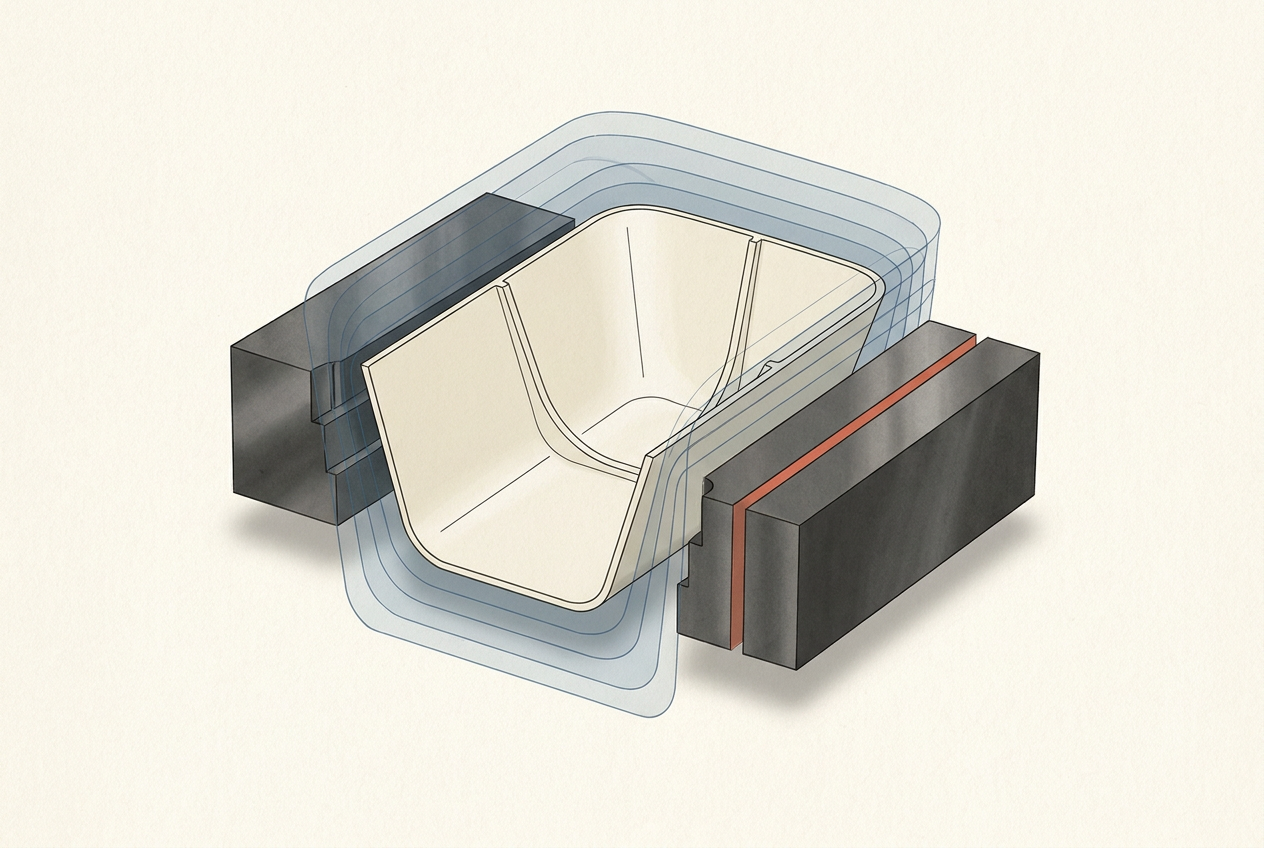
For injection moulding, I establish the pull direction before detailing walls and ribs. Draft gives surfaces clearance as the part separates from the mould. Protolabs' moulding guidance explains that the necessary angle depends on geometry and surface finish, among other factors. I treat any suggested starting angle as a discussion point, not permission to ignore depth, texture or material.
I use a draft analysis to find faces that oppose the intended pull direction, then inspect the functional consequences of adding taper. Over a 30 mm depth, one degree of draft changes a wall's lateral position by roughly 0.52 mm. That is geometry, not a supplier allowance. It can affect a mating edge or internal clearance, so I choose which end of the feature controls the critical dimension.
I then section the model to look for thick masses and abrupt thickness changes. These can create uneven cooling, sink and distortion. I consider coring out a thick boss or adding ribs rather than simply adding material, while checking strength and fastening needs. Rib and boss proportions need material-specific review. Undercuts get separate attention because they may require moving tooling, a redesign or an agreed demoulding method.
Find the features that increase manufacturing cost
My cost review starts with operations rather than material volume alone. I look for extra setups, deep pockets, small cutters, long threads, side actions, demanding finishes and inspection requirements. None is automatically wrong. Each needs a reason. A feature that saves assembly time may justify more expensive tooling; a decorative recess that adds machining time on every part may not.
I separate visible surfaces from contact surfaces and concealed surfaces. Specifying the same finish everywhere can buy work nobody needs. I also check coating and finishing allowances where fits matter. The relevant question is whether the finished component meets the requirement, not whether the unfinished substrate matches the nominal model. Coating thickness and masking requirements belong in that conversation.
When the cost driver is unclear, I ask for a comparison quote with one feature changed or removed. That gives me a useful trade-off instead of a vague request to make the part cheaper. For production decisions, I compare tooling, unit price, secondary operations, inspection and assembly over the expected quantity. I don't assume the process with the lowest tooling bill will have the lowest total cost.
Release a model and drawing that can be inspected
Before release, I check that the model, drawing and purchase requirements describe the same part. I define the material, applicable tolerances, finish, thread requirements and revision. I make clear which information governs if documents disagree, using the supplier's agreed workflow. A beautiful solid model still leaves room for expensive interpretation if nobody knows which surfaces locate the part or which edges need attention.
I review critical requirements with inspection in mind. Can the datum surfaces be contacted? Can the specified feature be measured after finishing? Does the measurement method suit the tolerance? Asme's framework helps express the requirement, but I still need agreement on practical acceptance. I avoid demanding inspection of every modelled dimension when only a smaller set controls fit, safety or performance.
For a first build, I request inspection results for the critical characteristics and test the assembly under its intended conditions. I record whether a failure came from the specification, the manufactured part or the assembly assumptions. Then I revise the right thing. If a supplier flags a difficult feature, I want the proposed geometry change, its functional effect and its cost implication before approving it.
Questions people ask
What is design for manufacturing in cad?
I treat it as modelling around the process that will make the part. That includes access, material behaviour, tolerances, assembly and inspection, rather than checking only shape and appearance.
What tolerance should I use for machined parts?
I start with the supplier's stated process capability and tighten individual requirements only when function demands it. There isn't one suitable tolerance for every material, feature size and machining operation.
How much draft does an injection moulded part need?
I agree draft with the moulding supplier based on depth, material, texture and ejection requirements. I don't treat one or two degrees as universally sufficient, particularly on deep or textured surfaces.
Do I need a drawing if I supply a 3d model?
I need an agreed way to communicate requirements that geometry alone doesn't establish. That may be a drawing or an accepted model-based definition, but material, tolerances, finish and acceptance requirements still need specifying.