2026-09-29 · 7 min · By Alcott Dube
Technical drawing for manufacturing: how to get a quote
I document parts around the decisions a shop must price: geometry, material, tolerances, finish, inspection and the assumptions that would otherwise trigger clarification calls.
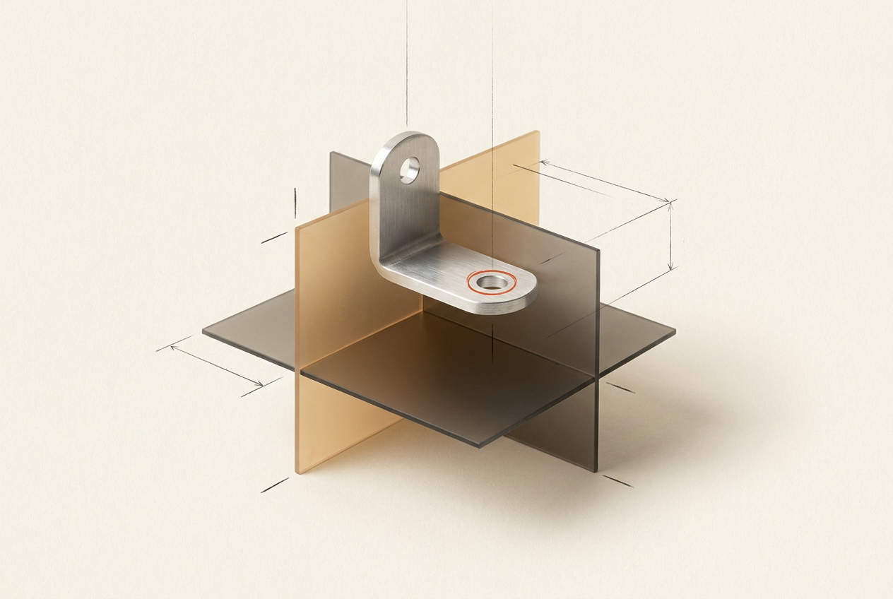
To get a manufacturing quote, I send a revision-matched model and technical drawing that define material, quantity, critical dimensions, tolerances, datums and finish. I make the acceptance criteria explicit, identify which file controls which information, and ask the shop to state any assumptions or exceptions in its quote.
What files does a machine shop need for a quote?
I start with a quote package, not an isolated drawing. For a machined part, that usually means a neutral solid model, a drawing in a portable document format, and a request stating quantity and required delivery date. A prototype quantity of two and a batch of 200 can justify different fixtures, stock choices and inspection methods.
The model carries shape. The drawing carries requirements that shape alone cannot communicate reliably: material condition, threads, fits, surface texture and inspection controls. Protolabs' machining guidance is useful here because it makes process limits visible. A feature can exist perfectly well in a model while remaining awkward to reach with a cutter.
I put the same part number and revision in both filenames and the drawing title block. I also state the intended process where it matters. If a supplier can propose another process, I invite that explicitly rather than leaving it to guess whether a cast alternative is acceptable.
Which views and dimensions belong on a manufacturing drawing?
I choose views around what needs explaining. A simple plate may need two orthographic views and an isometric reference. A stepped bore usually needs a section. A small groove may need an enlarged detail. More views are not automatically more useful, especially when they repeat dimensions and create another place for revisions to disagree.
For a model-based quote package, I dimension the overall envelope, mating features, hole patterns and anything the shop must inspect explicitly. I don't ask someone to measure a printed view. If the drawing must support manufacture without a model, it needs enough dimensions to define the geometry independently.
I define document authority rather than assuming the shop's convention matches mine. For example, the model can control undimensioned nominal geometry while the drawing controls stated tolerances and notes. I ask for conflicts to be raised before manufacture. That instruction does not repair contradictory files, but it prevents an informal choice from becoming an accepted requirement.
How to choose datums for a machined part
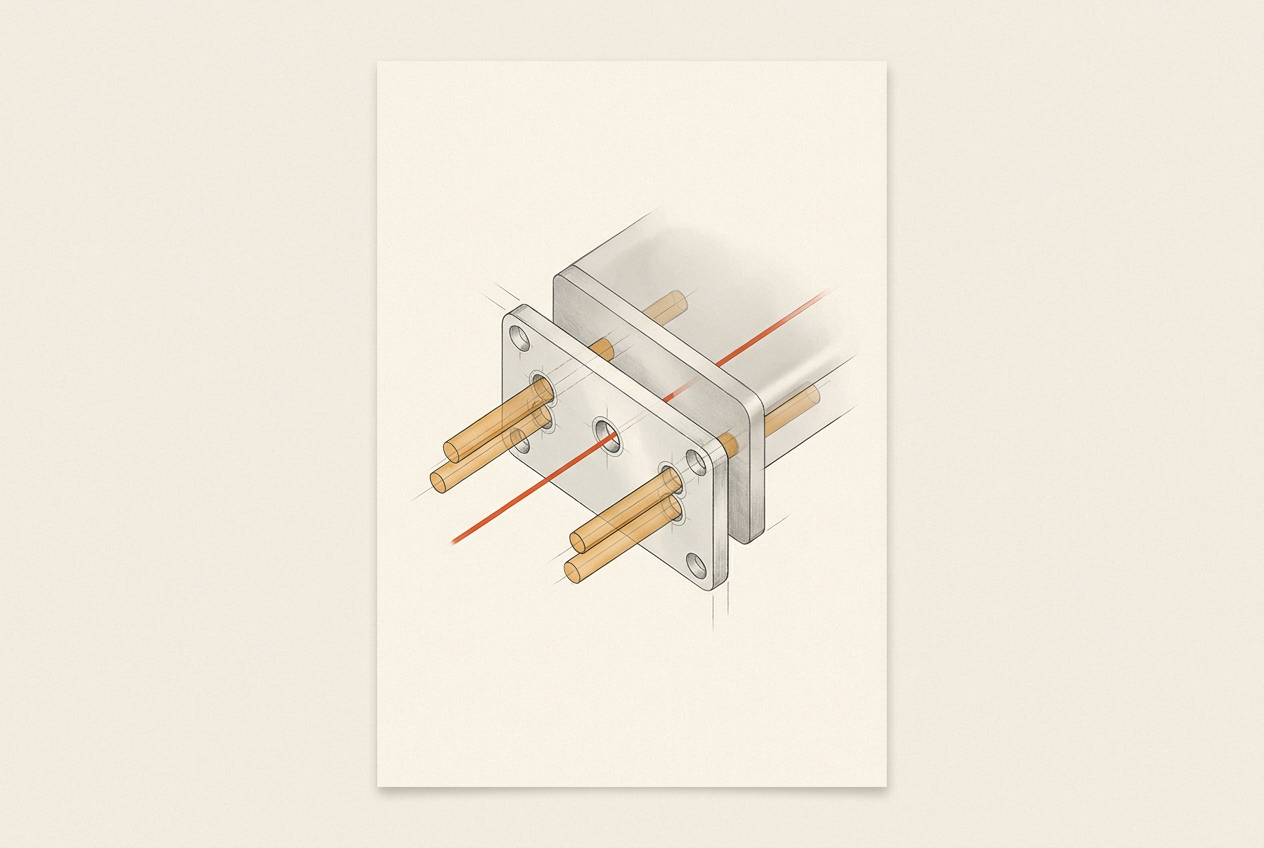
I choose datums from how the part locates in its assembly. For a bracket seated against a flat mounting surface, that face is a sensible primary datum feature. A locating side and an end face might establish the remaining references. Choosing the easiest corner to dimension from can produce a tidy drawing that controls the wrong relationships.
The distinction in asme y14.5 matters: the physical datum feature is not the same thing as the theoretically exact datum established from it. I identify actual surfaces or features the inspector can use. Three mutually perpendicular faces can establish a practical reference frame, but they are not the right answer for every part.
A turned component may function around an axis rather than three faces. A plate located by dowels may need its locating holes involved in the reference scheme. I check that each selected feature is accessible and repeatable during inspection. An unstable or poorly defined reference makes otherwise precise measurements difficult to interpret.
Which geometric tolerances do I actually need?
I use geometric dimensioning and tolerancing when size dimensions alone do not describe the functional requirement. A hole diameter controls size; it does not fully control where the hole sits relative to the assembly references. Position can control that relationship. Flatness can control a seating surface without referring to a datum.
For an illustrative four-hole mounting pattern, I might specify hole sizes, theoretically exact basic dimensions for their locations, and a position tolerance relative to the functional datum frame. I would choose the numerical tolerance from fastener clearance and the mating part's variation, not because a familiar value looks suitably precise.
I name the governing standard and edition, such as asme y14.5-2018. I don't mix conventions casually or add material-condition modifiers without understanding their effect on acceptance. Position, perpendicularity and profile solve different problems. If I cannot explain what failure a control prevents and how it will be checked, I reconsider whether it belongs on the drawing.
How tight should machining tolerances be?
I separate functional requirements from convenient defaults. A bearing seat and an external clearance face rarely deserve the same tolerance. Tightening every dimension can change the machining sequence, increase inspection effort and reduce yield, even when most of that precision adds nothing to the assembly.
For an illustrative clearance feature, a nominal 20 mm dimension with a tolerance of plus or minus 0.2 mm might be adequate. That is not a recommended fit for a bearing, dowel or sliding pair. I calculate those requirements from the mating parts, operating conditions and tolerance stack. I also check the supplier's published capability before treating a number as routine.
I give untoleranced dimensions an explicit general tolerance, with exceptions called out locally. Surface texture gets the same selective treatment: I specify it where sealing, friction or appearance requires it. Protolabs publishes process-specific limits and capabilities, but supplier capability is not a substitute for deciding what the part actually needs.
Which drawing notes prevent clarification calls?
I write notes that settle purchasing and acceptance decisions. Material needs a grade and, where relevant, condition or temper. 'Aluminium' leaves too much open. If alternatives are acceptable, I define the approval route. I also identify heat treatment, coating and any certification requirements before the quote, because each can affect cost and delivery.
Threads need a recognised designation, size, pitch or series, and tolerance class where applicable. Blind threaded holes need usable thread depth distinguished from drilled depth. I specify inserts when required rather than expecting the shop to infer them from the model. Similar-looking holes can involve quite different tooling and purchased components.
Edge and finish notes need boundaries. For example, I might allow a 0.2 to 0.5 mm edge break on otherwise unspecified edges, while protecting a sealing edge with a local instruction. For coated parts, I state masking requirements and whether controlled dimensions apply before or after coating. 'Deburr' alone does not settle those decisions.
How to check a drawing before requesting quotes
I review the package as a purchasing decision and an inspection problem. Can the shop identify the stock, reach the features, locate the part and verify acceptance? Deep narrow pockets, thin walls and small internal radii deserve attention before release. Protolabs' milling guidance provides a useful process check, although another supplier may have different equipment and limits.
I then compare every controlled feature against the model. I check hole counts, thread depths, units, revisions and coating allowances. Reference dimensions are marked as reference, not left looking like extra acceptance criteria. If inspection reports are required, I specify their scope and sampling expectations rather than assuming every dimension will be reported on every part.
When quotes return, I compare exceptions before prices. A lower figure that excludes finishing or relaxes a position tolerance is not the same offer. I ask suppliers to separate tooling, inspection and recurring part costs where useful, and keep proposed drawing changes subject to approval before manufacture.
Questions people ask
Can a machine shop quote from a 3d model alone?
Some shops can quote straightforward parts from a model using their default manufacturing terms. I add a drawing whenever threads, fits, finishes or inspection requirements differ from those defaults. Otherwise, the price may describe a different acceptance standard from the one I intended.
Do I need geometric tolerances on every part?
No. I use them where form, orientation or location needs control beyond ordinary size dimensions. A simple spacer may need very little, while a locating plate can need a carefully defined datum scheme and hole-position controls.
Should drawing dimensions apply before or after anodising?
I state this explicitly for affected dimensions. If a finished bore must achieve a particular fit, its acceptance requirement needs to account for the coating. The shop may need masking or a machining allowance, depending on the process.
What units should I use on a manufacturing drawing?
I use the unit system appropriate to the assembly and supplier, then state it clearly on the drawing. I check the model export uses the intended units too. Dual dimensions need clear precedence so rounding does not create competing requirements.